|
Glass Shell and Tube Heat Exchangers are of recent
development. These heat exchangers can be used for condensation of
vapours, vaporisation, cooling and heating of liquids.
The shell and tube heat exchangers are available in
various combinations of Glass/Metal/FRP in shell or headers. Glass
shells are constructed using standard glass components like pipe section,
tee, cross, etc. Metal shells are generally constructed of MS in one
piece.
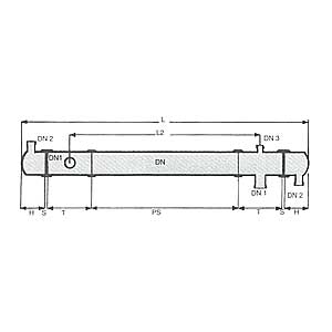
Shell and tube heat exchanger consists of a cylindrical
shell which houses a glass tube bundle. Tubes are sealed with shell
with the help of PTFE tube sheets. Each tube is individually sealed
by 'O' ring in tube sheets at both ends. Baffles are provided in the
shell to maintain state of turbulence of fluid as well as to hold the
tubes.
Shell and tube heat exchangers have come out to be more
advance and beneficial for its following advantages :
- Bigger heat transfer area in one unit.
- Less pressure drop.
- Stuffing box sealing allows easy tube replacement.
- Less maintenance.
|
|
Technical information
All the shell and tube heat exchangers are
constructed with 12mm OD, 1.5mm thick glass
tubes. These tubes are arranged in triangular
pitch of 21mm. Baffles are provided with 30% cut
at a distance of approximately equal to inner diameter
of shell. Generally, PTFE baffles are used in
Glass shells and PP baffles in Metal shells.
Shell and tube heat exchanger can be
operated within a temperature range of ~ 40°C to
150°C on either side. However, differential
temperature should not exceed 120°C at any
point. All the Shell and tube heat exchangers
can be used predominantly under full vacuum, provided
differential pressure does not exceed 3 bar g.
The range of overall heat transfer
co-efficient in the Shell and tube heat exchangers are
considered as follows:
Condensation :
Water -
Water
: 600-900 Kcal/m˛ ,h, °C
Condensation : Water - Organic
solvents : 400-600 Kcal/m˛
,h, °C
Evaporation
: Steam -
Water
: 500-900 Kcal/m˛ ,h, °C
Cooling
: Water -
Water
: 500-600 Kcal/m˛ ,h, °C
Cooling
: Water - Organic solvents
: 250-600 Kcal/m˛ ,h, °C
Cooling
: Water -
Oil
: 75-350 Kcal/m˛ ,h, °C
Cooling
: Water -
Air
: 25-250 Kcal/m˛ ,h, °C
|
| DN |
No.
of
Tubes |
Cross
section Cm˛ |
Max.
Operating Pressure |
Shell
Side |
Tube
Side |
Tube
Side |
Shell
Side |
| Glass |
Metal |
80
100
150
225
300 |
7
19
37
73
151 |
23
43
93
189
348 |
5
12
23
46
96 |
3.0
2.0
1.5
1.0
0.7 |
3.0
2.0
1.5
1.0
0.7 |
3.0
2.0
2.0
2.0
2.0 |
| Glass Shell |
|
|
Cat.
Ref. |
HTAm˛ |
DN |
DN1 |
DN2 |
DN3 |
L |
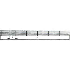
L1 |
L2 |
PS |
T |
S |
H |
B |
Baffles |
RGG6/1
RGG6/1.5
RGG6/2
RGG6/3
RGG9/4
RGG9/5
RGG9/6
RGG12/8
RGG12/11
RGG12/14
RGG12/16
RGG12/22 |
1
1.5
2.2
2.9
4.1
5.2
6.6
8.5
10.8
13.7
16.5
22.2 |
150
150
150
150
225
225
225
300
300
300
300
300 |
50
50
80
80
80
100
100
100
150
150
150
150 |
25
25
50
50
50
80
80
80
80
80
80
80 |
25
25
50
50
25
50
50
25
50
50
50
50 |
1050
1400
1900
2400
1900
2300
2800
1950
2350
2850
3350
4350 |
800
1150
1650
2150
1550
1950
2450
1550
1950
2450
2950
3950 |
500
850
1300
1800
1200
1450
1950
1100
1450
1950
2450
3450 |
250
600
1000
1500
900
1000
1500
700
1000
1500
2000
3000 |
250
250
300
300
300
450
450
400
450
450
450
450 |
25
25
25
25
25
25
25
25
25
25
25
25 |
125
125
125
125
175
175
175
200
200
200
200
200 |
148
159
135
156
223
192
205
332
259
256
328
299 |
4
6
10
12
6
8
10
4
6
8
8
12 |
| Each Shell and
tube heat exchanger is supplied with following spares :
DN 150-5 tubes, 4 plugs, 4 brushes, 4 'O' rings, 1
key.
DN 225-10 tubes, 6 plugs, 6 brushes, 6 'O' rings, 1 key.
DN 300-15 tubes, 8 plugs, 8 brushes, 8 'O' rings, 1 key.
Orientation of branches, if other than above, should
be specified in order.
Following accessories are recommended to use with
Shell and tube heat exchanger :
- PTFE bellows on all nozzles.
- Pressure relief valve.
- Supporting clamps. |
|
|
|